


1. Trace heating What is it? Why have it?
Electrical heating system is used in various industries to protect the freezing of pipes (such as gas) or to maintain fluid temperature inside the pipes or reservoirs.
- Due to varying ambient temperatures process conditions are upset
- Water based solutions may freeze in Winter
- Oil / Hydrocarbon based fluids will become viscous
- Chemicals may solidify
- Foodstuffs may separate
- Aromatics may not produce correct aromas
- Inks and dyestuffs lose consistency
- Product quality and yield suffers
When HEAT TRACING is needed
When it is needed that the temperature of the fluid (process) is greater than the ambient temperature, based on the rules of thermodynamics, fluid, as a heat source, begins to lose thermal energy, and when it is cooled to ambient temperature, the amount of lost energy per unit length / surface as HEAT LOSS will be calculated in this case to compensate HEAT LOSS, heating systems and especially electrical heating systems are used.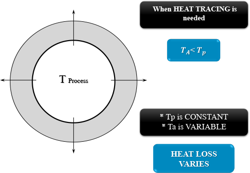
Heat Tracing Advantage
- Most industrial facilities will have electrical power available.
- A variety of types and methods of electric tracing may be used to maintain a broad range of temperatures for process pipes and associated equipment.
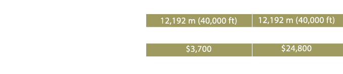
- Short lengths of pipe or long pipelines in the range of 60 kilometres in length may be heated by the use of various types of heating cables
- Electrical tracing is recommended for non-metal and lined piping and process equipment because of the ability to provide very low heat output.
- Electric tracing is often recommended for use with temperature sensitive products that must be maintained within a narrow temperature range.
- Simplified installation and reduced operation and maintenance costs.
- Over its history, electric tracing has proven to be a safe choice for process pipe and equipment heating.
POWER ON:
The maximum temperature can be tolerated by the heating cable when it’s on. Therefore, if the surface temperature reaches this temperature, it’s needed to be cut off the circuit by the temperature controller and heating cable exit from the circuit.
POWER OFF:
The maximum temperature at which the heating cable can stand in no charge (off) condition. Therefore, installing the cable on a surface that may have a temperature higher than the POWER OFF temperature is totally unauthorized.
HEAT-TRACE heating cables have this feature, which has the same two parameters, thus increasing the life of the cable and reducing the cost of the project due to no need for the thermostat to cut off the current at POWER ON temperature.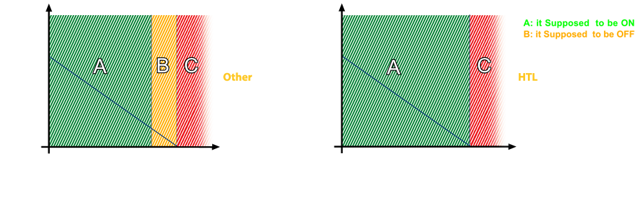
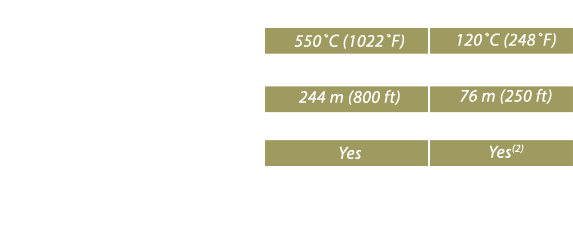
ELECTRICAL HEAT TRACE VS STEAM TRACE
Steam Tracing Historically, steam tracing has been used more often than any other type of pipeline heating, for freeze protection and for process heating. Steam typically has an advantage of having a high heat capacity combined with a suitable heat transfer coefficient. This high heat input has been advantageous in the past because thermal insulation systems on pipelines were often left for years without maintenance. When energy costs were negligible, this was an acceptable method of operation, since steam was perceived as being “free of costs”. When flowing through a tube, the steam will dissipate its latent heat to the process pipe to compensate for the loss in heat. During this process the steam temperature remains constant.
However when all steam condenses, the tube will then be filled with condensate which has a significantly lower heat capacity and a worse heat transfer coefficient. This process occurs gradually and along the entire length of the heating tube. Therefore it is necessary to install a steam trap at the end of the heating circuit to "trap the steam" and discharge the condensate with a minimum loss of fresh steam. Because the condensate in the heating tube has to be "pushed" to the steam trap (often upwards), the steam system must have sufficient pressure, which limits the maximum length of the heating circuits. Circuits which are too long will "drown" in condensate and the heat transfer will become very unpredictable and unstable, which adds complexity to the steam tracing system. The inherent result of the short heat tracing circuits is that valuable space in the process area is used for the steam distribution and condensate collection infrastructure. Steam traps are the most critical and at the same time most sensitive component of the steam tracing system. Due to the mechanical nature of the steam system with constantly moving parts often resulting in abrasion by the steam and blockage because of poor steam quality; steam traps are subject to frequent inspections (at least once annually) to ensure continued operation of which a significant number of the traps (roughly 6%) must be replaced each year. Energy waste is often high on steam-tracing systems. Steam being a constant temperature source, any non-flowing pipeline is elevated to the temperature of the steam-tracing circuit over a period of time. On flowing pipelines the steam will continually transfer energy to the fluid at a higher rate because the temperature differential between the steam and the fluid essentially stays constant. Both conditions provide more heat energy to the system than is required to maintain design conditions. To date, there is no reliable method for controlling the pipeline temperature and energy usage. Depending on the type of steam trap used; even under perfect working conditions, there will always be some loss of steam. If the traps fail-open, there will be a significant amount of steam loss especially because these systems are in operation 24/7. A brief technical differentiation between steam and electric heat tracing (mineral insulated) is provided in the table below.
Comparing Steam tracing to electric Heat tracing
Typically, an electric heat tracing system is approximately 75% of the total installed cost of a steam tracing system, when taking into account the tracing system, the control & monitoring, and the power distribution system.
The total installed cost will vary according to location and specific heat-input requirements, but remain constant as an industry average. Heat Tracing Solutions can perform a complete technical and economic analysis on a customer’s heat tracing system to determine the best value for that specific application.
From a safety perspective, there is a much higher probability of the potential for maintenance personnel to be susceptible to burns while working on and around steam-traced systems due to the exposed valves and traps. Electric heat tracing on the other hand, is intrinsically safe since it has no exposed circuits and also has ground fault protection.
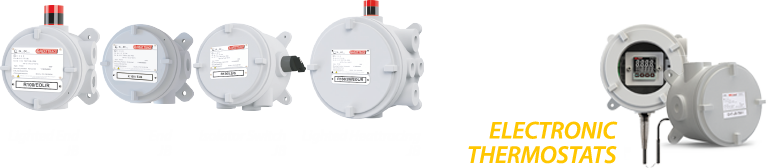
Electrical heating systems can include a wide variety of control and monitoring products, from simple mechanical thermostats and signal lights to sophisticated multi-circuit digital controllers. These control products vary the output of the heating source to keep pipes from freezing or to maintain process piping at elevated temperatures. From a maintenance perspective, with the electric heating system, most maintenance can be based on results from control and monitoring incorporated into the design of the system itself.
Steam-tracing systems, on the other hand, do not offer any reasonable form of control and monitoring. The largest maintenance items in a steam tracing system are the steam traps, as they are typically the items which are most likely to fail during operation. The documented service life of a typical steam trap is three years, with a minimum replacement cost of approximately $95. As a result, it is also recognized that the maintenance of the condensate return is always higher than that of the steam supply, as the liquid and steam cause erosion of the elbows in the system. This is why many condensate return systems are constructed of stainless steel.
The chart shown below provides an example of where the maintenance costs of the electrical heat-tracing and steam-tracing systems are compared for a process maintenance heating application.
2. Applications
a. INDUSTRIAL
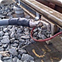
vii. Rail & Points Heating
vi. Instrumentation
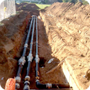
v. Buried Pipelines
iv. Long Pipelines
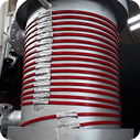
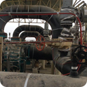
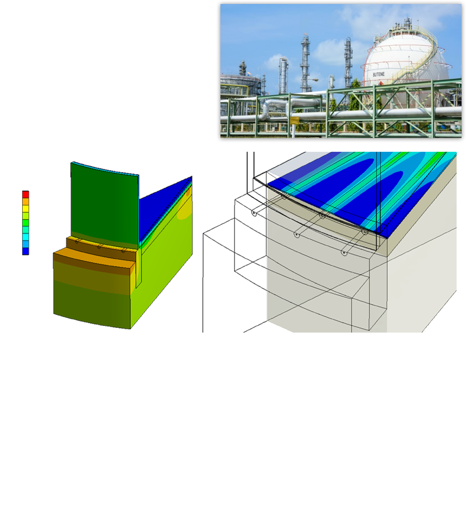
iii.Tank &
Vessel
Heating
ii. Process Temp
Maintenance
i. Freeze Protection
b. COMMERCIAL
vi. Heating of Fuel Tanks
v. Hot Water Heating
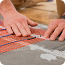
iv. Under Floor Heating
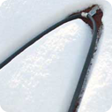
iii. Snow & Ice Melting

ii. Roof & Gutter Heating
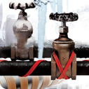
i. Freeze Protection
c. TRACE HEATING PROCESS APPLICATION TYPES
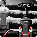
- Freeze Protection:
- Temperature maintenance:
- Raise and Maintain Temperature :
The application of heating cable to pipe work/plant carrying water or aqueous based solutions to prevent freezing
The application of heating cables to pipework and plant to maintain their contents at a specific temperature above the lowest expected ambient conditions
The application of heating cables to pipe work and plant to raise the pipe and contents from a low start-up temperature to a specific maintain temperature above the lowest expected ambient conditions within an agreed period of time. This may also include a change of state of product or may be required under flow conditions.
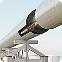
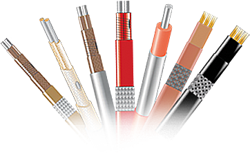
3. Heat Tracing System - Components
The components of the electrical heating system include Heath tracing cable with installation, control and monitoring equipment and implementation of an appropriate insulation coating is essential to maintain the temperature and proper system operation.
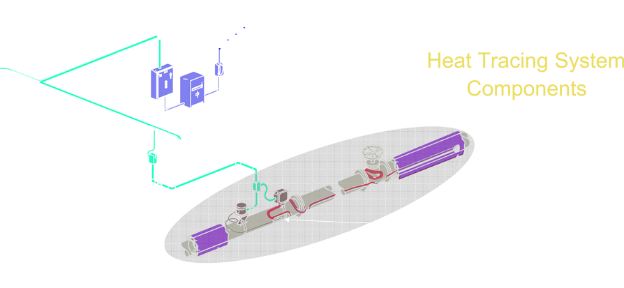
System Component:
A. Heat Trace Cable
B. Termination and Installation Components
C. Control and Monitoring
D. Insulation
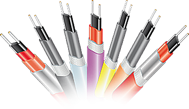
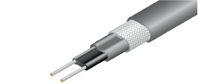
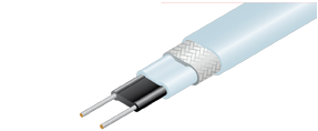
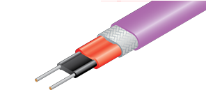
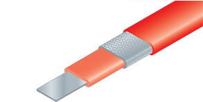
A. Heat Trace Cable
The heating system cables in terms of energy production are in 2 types of self-regulation and constant power, which are selected regarding to design and use.
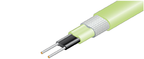
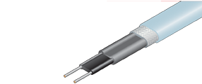
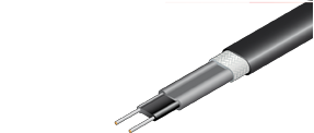
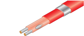
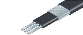
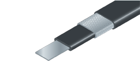
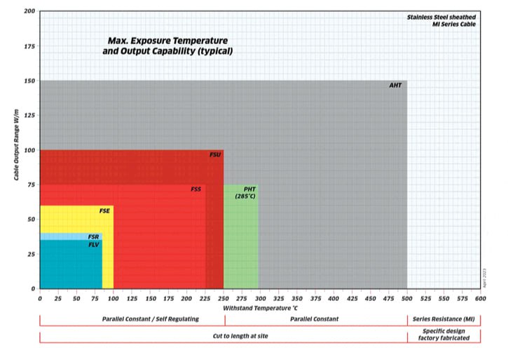
A.1. Parallel Self-Regulating Heaters
Semi conductive parallel resistance heating cables mainly for use in freeze protection or temperature maintenance applications. Approved for use in both safe and hazardous areas. For use up to 300°C (572°F).We can produce self-regulating heating cables within the following ranges:
- 12 - 1000 Volts
- Up to 300°C (572°F) withstand temperature
- Up to 120 W/m of output
Low Temperature
FREEZSTOP MICRO
FSM withstand tempraturas - 65°C
energised / 85°C un-enegised.
FREEZSTOP LITE
FSLe withstand tempratures - 85°C
energised / 85°C un-enegised.
FREEZSTOP REGULAR
FSR withstand tempratures - 85°C
energised / 85°C un-enegised.
FREEZSTOP EXTRA
FSE withstand tempratures - 100°C
energised / 100°C un-enegised.
CONDUCTOR RAIL HEATER
CRH maximum tempratures
135°C un-enegised./ minimum installation temperature -40°C
FREEZ STOP LOW VOLTAGE
FLV maximum exposure temperature
85°C energised
maximum exposura
temperature 85°C
G-TRACE
GT ambient temperature
range +60°C to -40°C
High Temperature
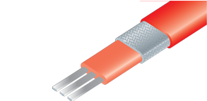
FAILSAFE +
FS+ withstand temperatures - 225°C
energised / 225°C un-enegised.
FAILSAFE SUPER
FSS withstand temperatures - 225°C
energised / 225°C un-enegised
FAILSAFE ULTIMO
FSU withstand temperatures - 250°C
energised / 250°C un-
enegised.
Very High Temperature
FAILSAFE ULTIMO+
FSU+ withstand temperatures - 275°C
energised / 275° un-enegised.
AUTO FAILSAFE
AFS withstand temperatures - 300°C
energised / 300°C un-enegised.
(reduced to 275°C when
overjacket is provided).
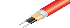
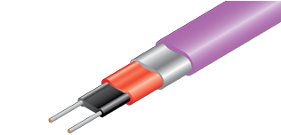
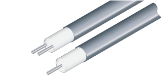
A.2. Parallel Constant Power Heaters to 500 °C
Constant Wattage heating cables (zonal heating cables) can be conveniently cut-to-length, but are less popular than self-regulating heating cables, because they often require thermostatic control to ensure temperature safety.Suitable for use in both safe and hazardous areas. We can produce constant wattage heating cables within the following ranges:
- 12 - 1000 Volts
- Up to 425°C (797°F) withstand temperature
- Up to 200 W/m of output
Low and Medium Temperature

MICROTRACER
Withstand Temperature up to 200°C
MINITRACER
Withstand Temperature up to 200°C
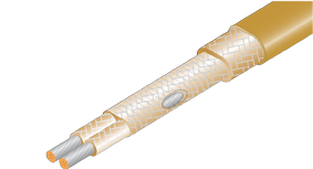
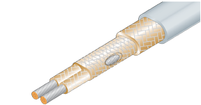
Mineral High Temperature
MINERAL INSULATED - MAL
Withstand Temperature up to 800°C
High Temperature
POWERHEAT - PHT
Withstand Temperature up to 285°C
POWERHEAT - RHT / RHT / U
Withstand Temperature up to 425°C
POWERHEAT - AHT
Withstand Temperature up to 500°C
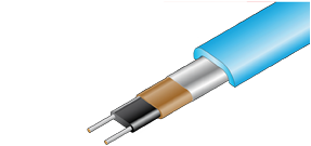
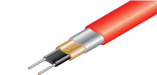
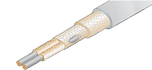
A.3 Series Resistance Heaters (LONGLINE ) to 230°C
Series Resistance heating cables have to be individually designed into particular length and load configurations and so are not as versatile as parallel cables. Suitable for use in both safe and hazardous areas. We can produce series resistance heating cables within the following ranges:
- Up to 6.6 kV 3 phase
- Up to 230°C (446°F) withstand temperature
- Up to 60 W/m of output
- Up to 100 km of maximum circuit length
Low Temperature
LONGLINE - HTP3F
Withstand Temperature up to 125°C
LONGLINE - HTP1F
Withstand Temperature up to 125°C
Medium Temperature
LONGLINE - HTS3F
Withstand Temperature up to 230°C
LONGLINE - HTS1F
Withstand Temperature up to 230°C
High Voltage

B. Termination and Installation Components
B.1. Terminations - power end
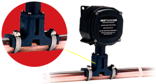
Direct Entry Sealed Termination Unit (DESTU)
This is an improved method, where the j unction box is connected to the DESTU, which is mounted onto the pipe surface. The tracer passes through the DESTU into the junction box, avoiding the possibility of damage to the tracer where it exits the thermal insulation.
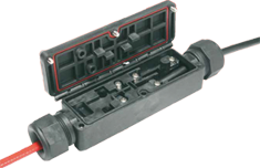
Strip Free Unit (SF/T or SF/P)
The Strip Free connection box has been specially developed by Heat Trace to reduce installation time and component costs. Tracers can be terminated without the need to strip the ends of self-regulating tracers. Strip Free units are available for connection to the power supply and also for series and tee connections. Strip Free boxes are particularly useful for small diameter instrument lines which cannot support large junction boxes.
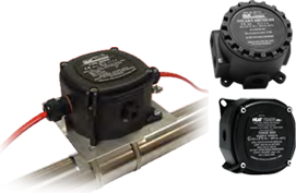
Standard Method
This uses tracer termination gland components and a junction box. To avoid the possibility of damage to the tracer where it exits from the thermal insulation, a separate lagging entry kit is required.
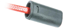
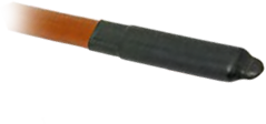
B.2. Terminations - remote end
Moulden end seal
The silicone rubber end seal is fixed with an adhesive. It is a simple and low cost form of sealing.

Strip Free End seal (SF/E)
The silicone rubber end seal is fixed with an adhesive. It is a simple and low cost form of sealing.
Heat Shrink seal
The silicone rubber end seal is fixed with an adhesive. It is a simple and low cost form of sealing.
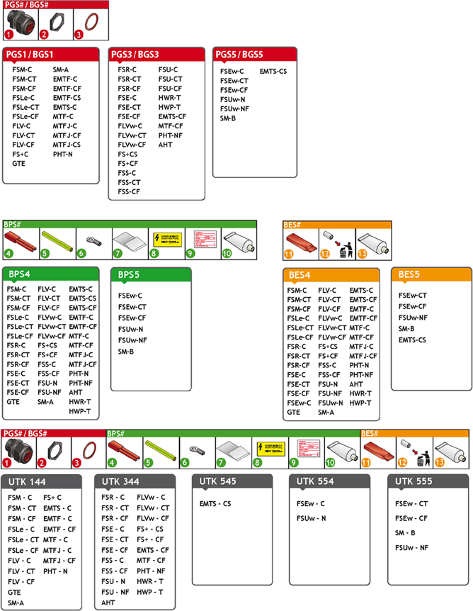
Termination Components & Respective Heating Cables
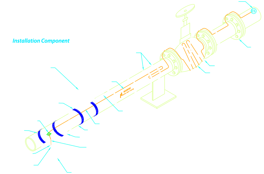
B.3. Installation Components
A range of miscellaneous components for use when installing Heat Trace products:
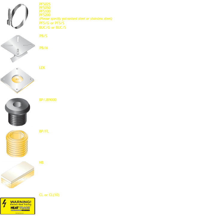
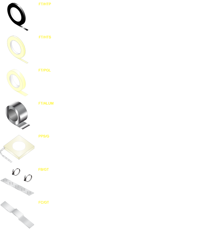
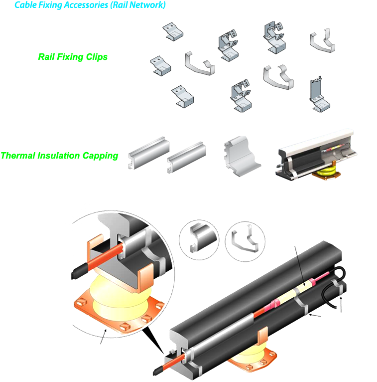
B.4. Cable Fixing Accessories
A range of adhesive and non-adhesive fixing methods for securing heating cable in position:
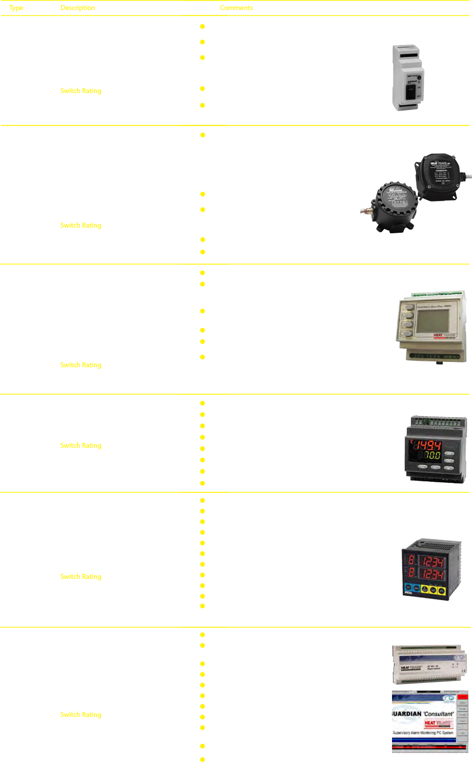
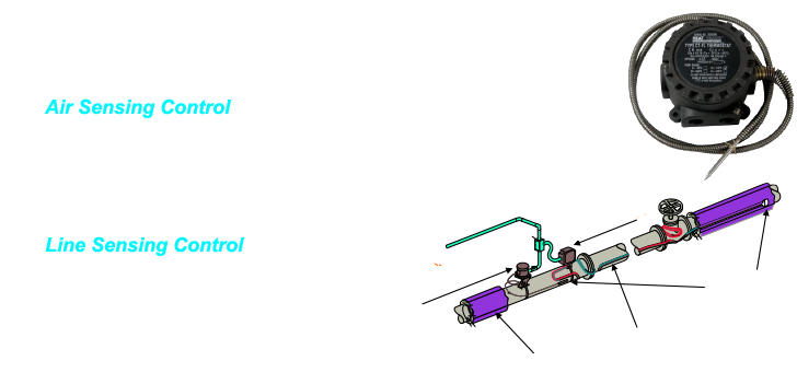
C. Temperature Control
Selection Guide
Type I process control - maintaining above a minimum temperature level
- is very energy wasteful. Not recommended-upgrade to Type II process control.
- can be achieved by air-sensing Power Match control to provide good energy efficiency from the fewest number of heating circuits i.e. least capital cost
- can be achieved by air-sensing Power Match control plus fine-tune line control to provide good energy efficiency from the fewest number of heating circuits.
Type II process control - maintaining within a broad temperature band
Type III process control - maintaining within a narrow temperature band
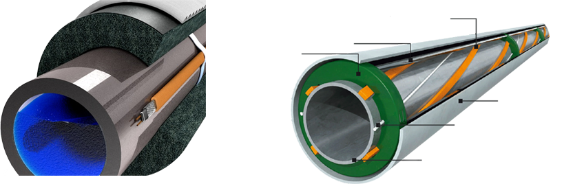
D. Insulation
Precautions must be taken to protect tracers from mechanical damage and moisture intrusion after they have been installed and prior to the application of thermal insulation. The installation supervisor shall coordinate with the thermal insulation contractor, so that the thermal insulation is applied as soon as possible after the installation and testing of heat tracers.
It should be confirmed that the thermal insulation to be installed is of the size, specification and thickness used for the design of the heat tracing system. When a tracer is installed onto the surface of a pipe, it’s effective diameter is increased. The thermal insulation is usually provided in pre-formed sections. Thus a small gap may occur due to the addition of the tracer. In this case, ‘filler’ segments should be installed to ensure full insulation.
Note that, if over-sized insulation is used (i.e. the next pipe size up), then heat loss calculations must be based on the over-sized pipe value.
Visual inspection
Carry out a visual inspection of the thermally insulated system to ensure that:
- moisture cannot penetrate the insulation
- screws used for fastening cladding are short enough to preclude any possibility of damage to tracers or temperature sensors.
- entry cut-outs in the cladding for heat tracers, temperature sensors, etc.., are dimensioned so as to render contact impossible.
- cladding joints and thermal insulation entries are properly sealed with an elastic, non-hardening sealant resistant to chemical attack.
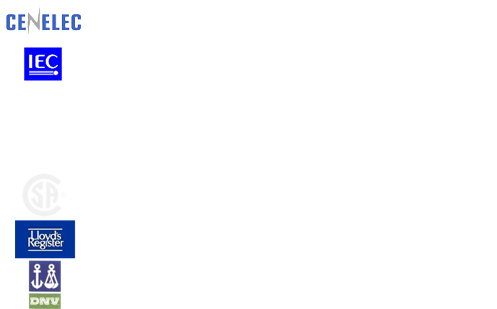
4. Standards & Approvals
Heat Trace takes and active part in the development and implementation of electric heat tracing industry standards.
Heat Trace’s products conform to several International Standards, some of which are shown below:
5. DESIGN (ORDER LINK)
- Establish Design Parameters
- Determine Heat Losses
- Select the Proper Heating Cable
- Determine Heat Tracing Circuit Lengths
- Control Selection
- Choose Options/Accessories

Step1. Establish Design Parameters
Piping / Equipment
- Pipe size
- Pipe length
- Pipe material
- Type and Number of Equipm
- Type and number of support
Temperature
- Min Ambient Temperature
- Start-up Temperature
- Maintain Temperature
- Maximum exposure Temp
- High Temperature – Limits
Electrical
- Electrical area classification
- Circuit Breaker capacity
- Operating Voltage
Insulation
- Type
- Thickness
Step2. Determine Heat Losses

Safety Factor Considerations
- Thermal insulation degradation
- Supply voltage variations
- Branch wiring voltage drop
- Heating device voltage drop (if applicable)
- Increased radiation and convection on higher temperature applications
- Quality of installation of thermal insulation
Calculating the Heat Loss of Vessel & Tank
Step3. Select the Proper Heating Cable
In order to determine the correct heating tape or cable according to the application the following information will be necessary
- Maintenance temperature
- Max. exposure temperature
- Pipe or surface material
- Supply voltage
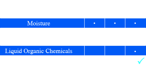
- Chemical environment
- Area classification
- Heat requirement
Step 3.1: Select Heating Cable Family
Step 3.2: Select Heating Cable Construction Options
Step 3.3: Select Thermal Output Rating
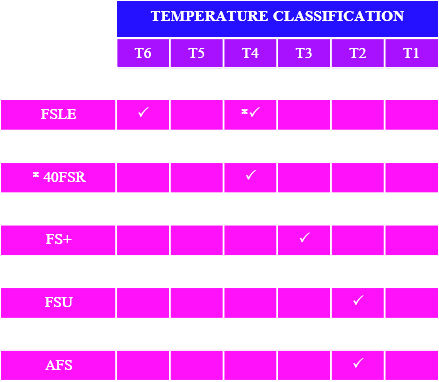
Step 3.4: Check T-Ratings
Step 3.5: Select Voltage Rating and Adjust for Alternate Voltages
Step 3.6: Determine Heat-Trace Part Number
Step 3.1: Select Heating Cable Family
Step 3.2: Select Heating Cable Construction Options
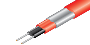
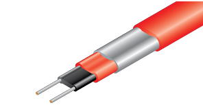
- C option cable is constructed with a tinned copper grounding braid only.
- CT/S option cable is constructed with a tinned copper braid and Thermoplastic/Silicon Rubber over jacket.
- CF option cable is constructed with a tinned copper braid and Fluoro polymer over jacket.
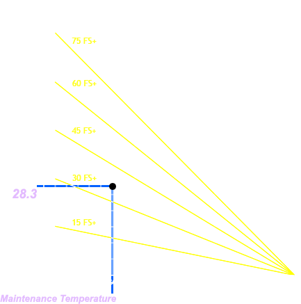
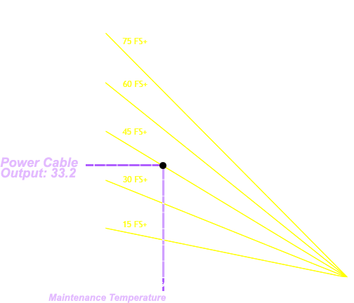
Step 3.3: Select Thermal Output Rating
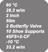
Example:
In the step above, we have chosen the FS+ cable family and our piping is metallic. Therefore, refer to cable data sheet, Calculated heat loss, Q, is (28.3 W/m). Find this point on the Y-axis. Maintenance temperature is (60ºC). Find this point on the X-axis. Choose the cable that lies above this point on the graph.
Step 3.4: Check T-Ratings
Step 3.5: Select
Voltage Rating and Calculate
Power Cable Out Put
Step 3.6: Determine Heat-Trace Part Number

Step 4 Determine Heat Tracing Circuit Lengths
Circuit Breaker Selection
To select the circuit breaker size, determine the following information:
- Maintenance Temperature
- Heat Loss per Meter of Pipe, QT
- Pipe or Tubing Size
- Pipe Length
- Type and Number of Valves
- Type and Number Supports
- Heating Cable Catalog Number
- Minimum Start-Up Temperature
- Heating Cable Out put
Step 4.1: Determine the Total Cable Length
Pipe length of 50 m single pass application
2 Butterfly Valves, additional cable 0.6 m each valve
10 Pipe Shoe Supports, additional cable per support is 0.6 m
= 50m 45FS+2-CF
=1.2m 45FS+2-CF
= 6m 45FS+2-CF
Total Cable length required = 57.2 m 45FS+2-CF
Step 4.2: Determine the Total Cable Length
- Finding the heating cable type
- Minimum expected start-up temperature
- From Heating cable Data Sheet select the circuit breaker trip rating
- Compare the maximum circuit length for each breaker rating to the total cable length required for each pipe.
- Select the breaker rating whose maximum circuit length just exceeds the total cable required for the pipe.
Number of Circuits = Total Cable Length / Maximum Circuit Length
Step 5: Control Selection
Step 6: Choose Options/Accessories
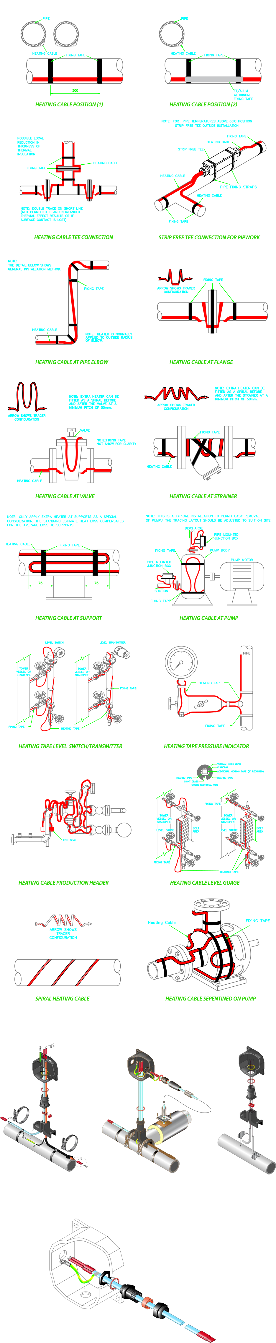
6. Installation Detail
- CABLE INSTALLATION TECHNIQUE
- THERMINATION TECHNIQUE
- PRE-COMMISSIONING REPORT
- COMMISSIONING REPORT


For more information visit our products pages
